Cryogenic Heat Exchanger Icing in Nitrogen Plants

Understanding the causes, symptoms, and engineering solutions for cryogenic heat exchanger icing in nitrogen plant cold box systems.

Cryogenic Heat Exchanger Icing

Cryogenic nitrogen plants rely on highly efficient heat exchangers to cool incoming air and establish the low temperatures required for cryogenic separation. These heat exchangers, commonly plate-fin or brazed aluminum designs, operate under extremely low temperature conditions inside the cold box.

However, when contaminants such as moisture or carbon dioxide enter the cryogenic section, they may freeze within the heat exchanger passages. This phenomenon is known as cryogenic heat exchanger icing.

Icing can restrict flow passages, increase pressure drop, disturb heat transfer efficiency, and disrupt the stability of the entire cryogenic separation process.

Understanding the causes and early symptoms of cryogenic heat exchanger icing helps plant engineers detect the problem early and prevent severe operational disturbances.

🔷Quick Engineering Summary for Plant Engineers

• Cryogenic heat exchanger icing occurs when moisture or CO₂ freezes inside exchanger passages.
• Icing increases pressure drop across the cold box heat exchanger.
• Disturbed heat transfer can destabilize column temperature profiles.
• Upstream air purification problems are the most common cause.
• Early detection helps prevent major plant operational disruptions.

Operational Symptoms of Cryogenic Heat Exchanger Icing

When icing begins to develop inside the cryogenic heat exchanger, several operational indicators may appear before significant process instability occurs. 

Disturbances in heat exchanger performance can also contribute to nitrogen purity fluctuation in cryogenic nitrogen plants.

Increasing Cold Box Pressure Drop

Ice accumulation inside heat exchanger passages restricts airflow and increases pressure drop across the cold box.

Reduced Nitrogen Purity

Disturbed temperature profiles may reduce the efficiency of nitrogen separation.

Distillation Column Temperature Instability

Changes in heat exchanger performance affect column temperature balance and separation stability.

Cold Box Temperature
Profile Disturbance

Heat exchanger icing disrupts heat transfer efficiency and causes abnormal temperature gradients.

Unstable Plant Operation

Flow restrictions and refrigeration imbalance may cause fluctuating process parameters.

Gradual Loss of Plant Capacity

Restricted flow through the heat exchanger may limit overall plant throughput.

Why Cryogenic Heat Exchanger Icing Matters

Cryogenic heat exchangers are among the most critical components in a nitrogen plant cold box. They enable efficient heat transfer between incoming air streams and returning cryogenic gases, allowing the plant to reach the extremely low temperatures required for nitrogen separation.

When icing develops inside the heat exchanger, the narrow plate-fin passages can gradually become restricted. Even small ice deposits can disturb heat transfer efficiency and increase resistance to airflow through the exchanger.

If the problem continues to develop, several operational impacts may occur:

Increased Cold Box Pressure Drop

Ice accumulation inside the exchanger restricts flow passages, leading to a gradual increase in pressure drop across the cold box.

Disturbance in Temperature Profiles

Heat exchanger icing disrupts the intended heat exchange process, causing abnormal temperature gradients within the cold box.

Reduced Nitrogen Separation Efficiency

Unstable temperature conditions can affect the performance of the distillation column and reduce nitrogen purity.

Loss of Plant Capacity

Restricted airflow through the exchanger may limit plant throughput and reduce overall production capacity.

Risk of Operational Instability

Severe icing can destabilize plant operation, potentially leading to automatic shutdowns or plant trips.

Understanding why cryogenic heat exchanger icing matters helps plant engineers recognize early warning signs and maintain stable operation of cryogenic nitrogen plants. Continuous monitoring of purification system performance and cold box operating conditions is essential to prevent exchanger icing and maintain reliable plant performance.

Major Causes of Cryogenic Heat Exchanger Icing

Cryogenic heat exchanger icing typically develops when trace contaminants or operational instabilities allow freezing substances to accumulate within the plate-fin heat exchanger passages.

These deposits gradually restrict flow channels, disturb thermal exchange performance, and increase pressure drop across the cold box.

In cryogenic nitrogen plants, icing issues are usually linked to air purification system performance, operating stability, or process contamination

Moisture or carbon dioxide entering the cryogenic section is often related to molecular sieve failure in nitrogen plant purification systems.

Below are the most common engineering causes.

1. Incomplete Moisture Removal in Air Purification System

Cryogenic processes require extremely dry feed air.
If molecular sieve dryers do not fully remove moisture, residual water vapor can freeze at cryogenic temperatures inside the heat exchanger.

Even very small moisture concentrations can eventually form ice layers within the plate-fin passages, reducing heat transfer efficiency.

2. Carbon Dioxide Breakthrough

Carbon dioxide solidifies at cryogenic temperatures and can accumulate inside the heat exchanger core.

If the air purification system allows CO₂ breakthrough, dry ice can form on exchanger surfaces and flow passages.

This can quickly cause localized blockage and cold box pressure rise.

3. Molecular Sieve Regeneration Problems

Improper regeneration of adsorption beds is a frequent root cause of icing events.

If regeneration temperature, purge flow, or cycle duration is insufficient, moisture and CO₂ remain trapped in the adsorbent material.

These contaminants can later pass into the cold box and freeze within the heat exchanger.

4. Adsorption Bed Channeling or Adsorbent Degradation

Mechanical degradation or channeling inside molecular sieve beds can reduce adsorption efficiency.

When air bypasses the active adsorption zones, contaminants are not properly removed.

Over time, this leads to increased contaminant load entering the cryogenic section, increasing icing risk.

5. Feed Air Contamination from Upstream Equipment

Oil carryover from air compressors, contaminated filters, or hydrocarbon ingress can also contribute to heat exchanger fouling.

These contaminants may freeze, condense, or accumulate within the plate-fin heat exchanger structure.

Such deposits disrupt thermal exchange and can gradually lead to icing-like blockage conditions.

6. Cold Box Temperature Instability

Unstable operating conditions in the cold box can accelerate icing formation.

Sudden drops in temperature or abnormal refrigeration distribution may cause localized freezing zones inside the exchanger.

Temperature instability often develops during:

  • startup operations

  • plant trips and restarts

  • expander performance fluctuations

These conditions increase the probability of ice formation within exchanger passages.

Diagnostic Approach Used by Plant Engineers for Heat Exchanger Icing

When icing develops inside a cryogenic heat exchanger, plant engineers must diagnose the problem carefully because the exchanger is located inside the cold box and cannot be visually inspected during operation.

Instead, engineers rely on process data analysis, pressure trends, temperature profiles, and air purification system performance to identify the root cause of icing.

A structured diagnostic approach helps determine whether the issue originates from air contamination, adsorption system problems, or cold box operating instability.

Icing events are sometimes observed during unstable plant startup conditions similar to those described in startup instability in cryogenic nitrogen plants.

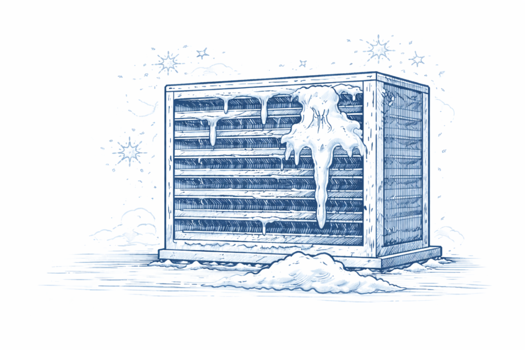
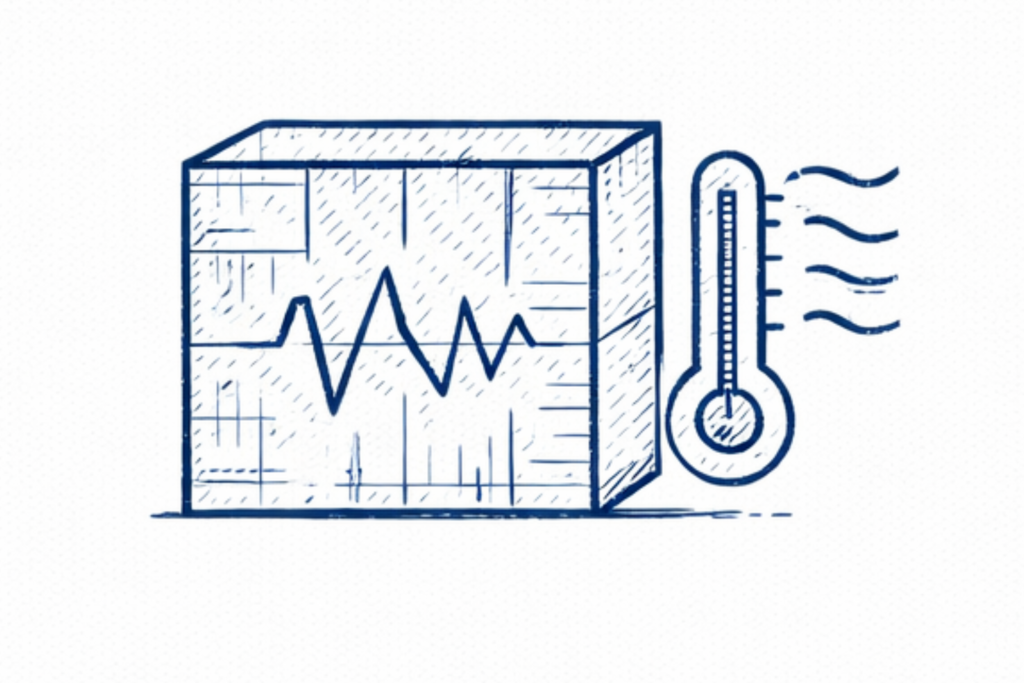
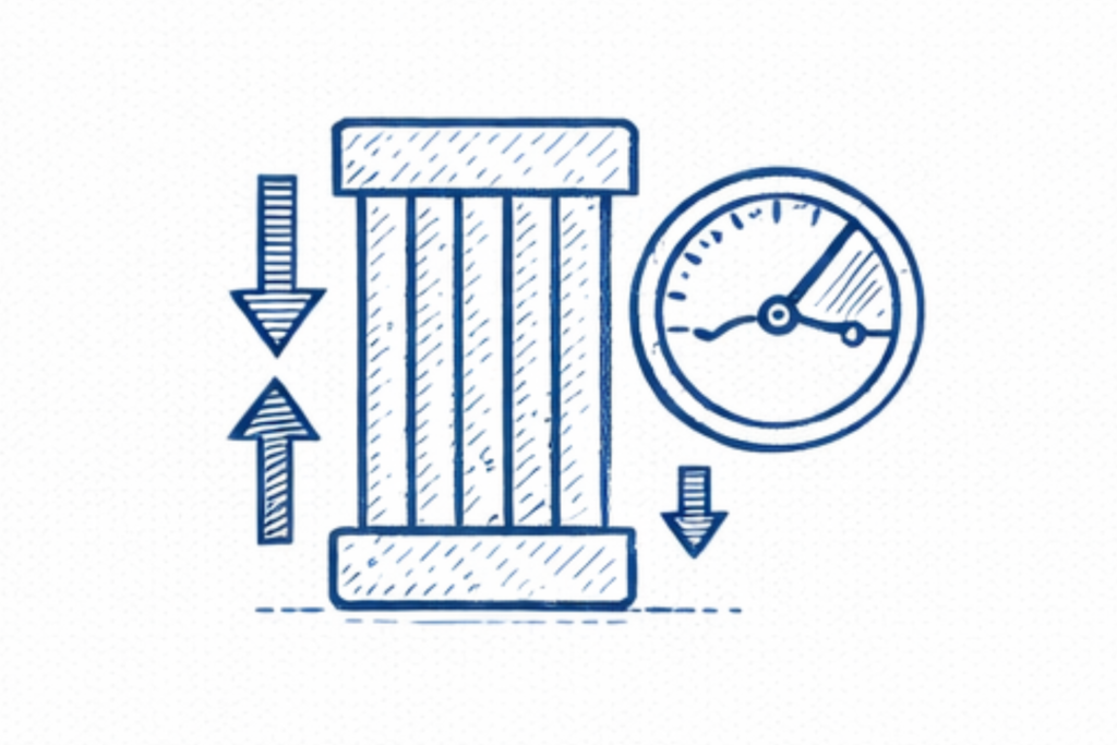
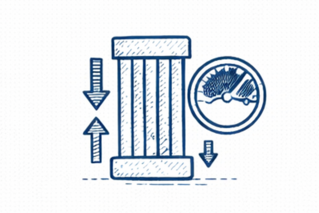
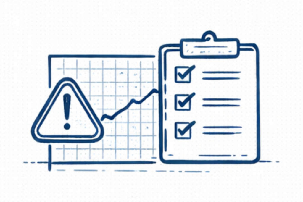
1. Cold Box Pressure Drop Analysis

The first diagnostic indicator is usually an increase in pressure drop across the main heat exchanger. Engineers compare historical plant data with current operating values to identify abnormal pressure rise. A gradual increase in differential pressure often indicates progressive ice accumulation inside exchanger passages.

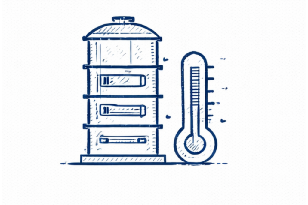
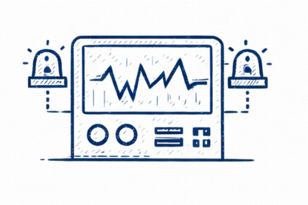
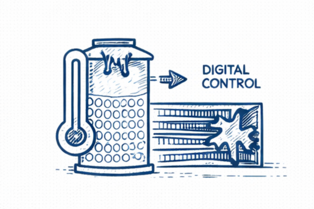
2. Cold Box Temperature Profile Review

Temperature sensors installed along the cryogenic heat exchanger provide important diagnostic clues. Engineers review temperature profiles to detect: abnormal cold spots unstable temperature gradients sudden deviations from normal operating patterns Irregular temperature distribution may indicate restricted flow caused by ice formation.

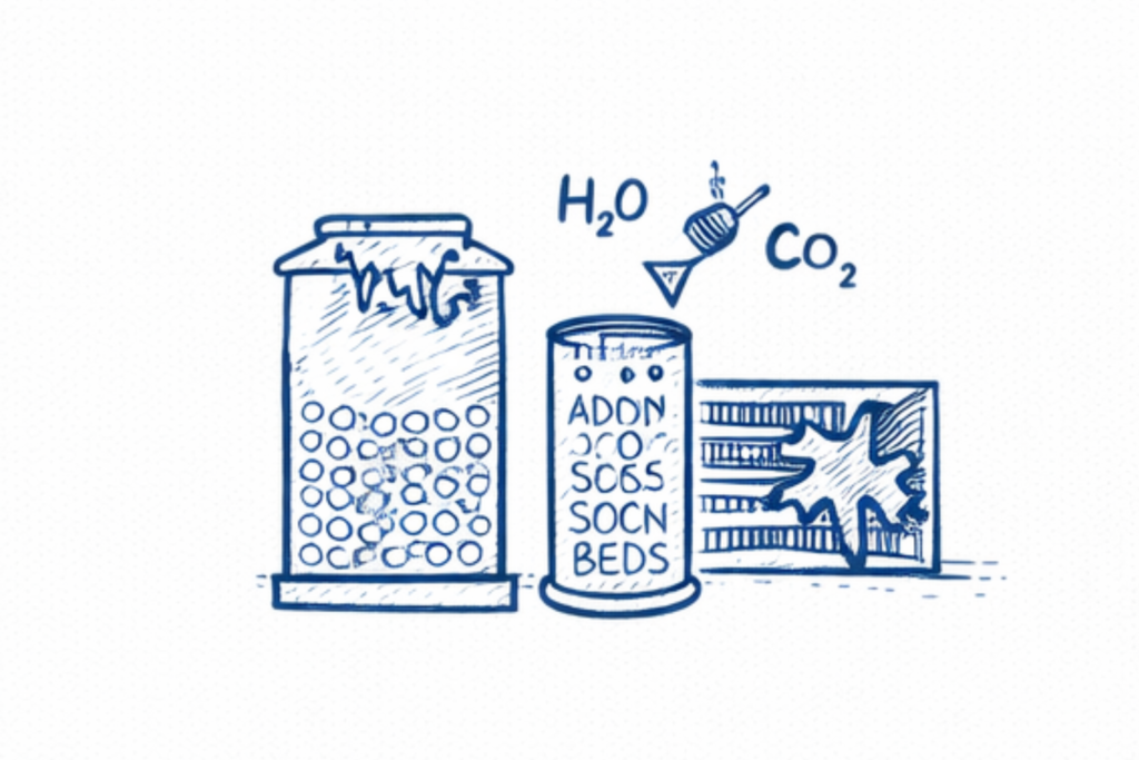
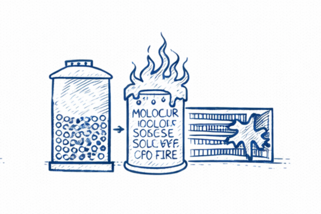
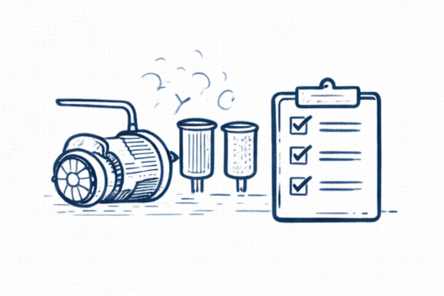
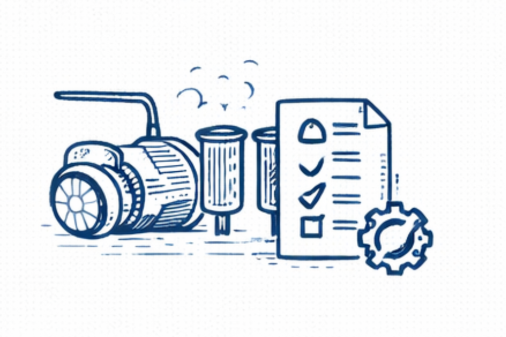
3. Air Purification System Performance Check

Since icing is frequently caused by contaminants entering the cryogenic section, engineers examine the molecular sieve purification system. Typical checks include: adsorption cycle timing regeneration temperature regeneration gas flow rate valve switching sequence Any abnormality in these parameters may allow moisture or CO₂ to pass into the cold box.

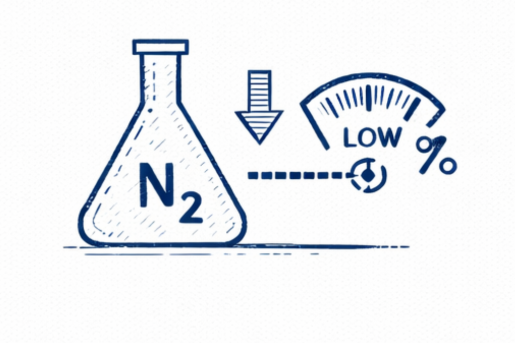
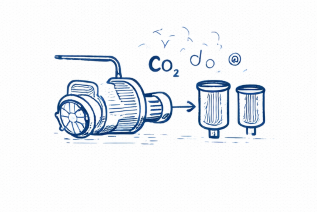
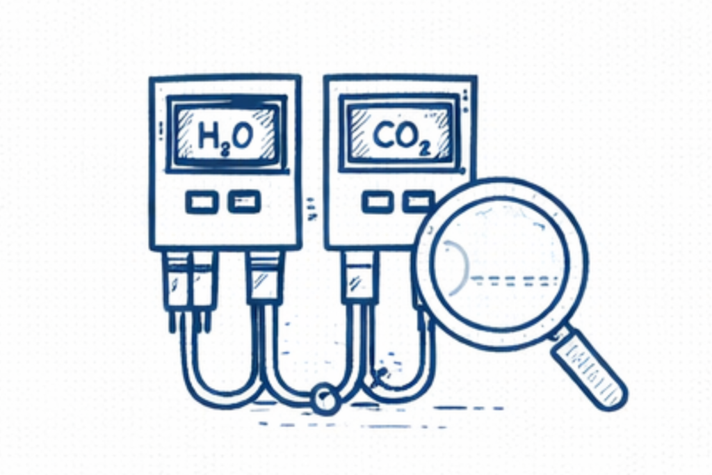
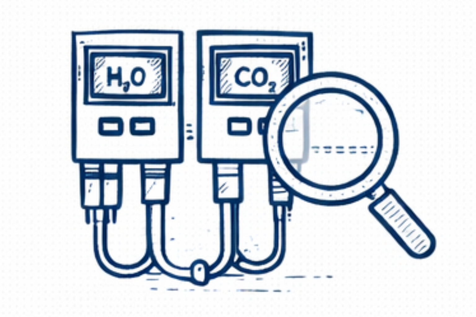
4. Moisture and CO₂ Analyzer Verification

Online analyzers are used to monitor contaminant levels upstream of the cold box. Plant engineers verify analyzer readings to confirm whether moisture or carbon dioxide breakthrough has occurred. Analyzer malfunction or calibration errors can sometimes hide contamination issues.

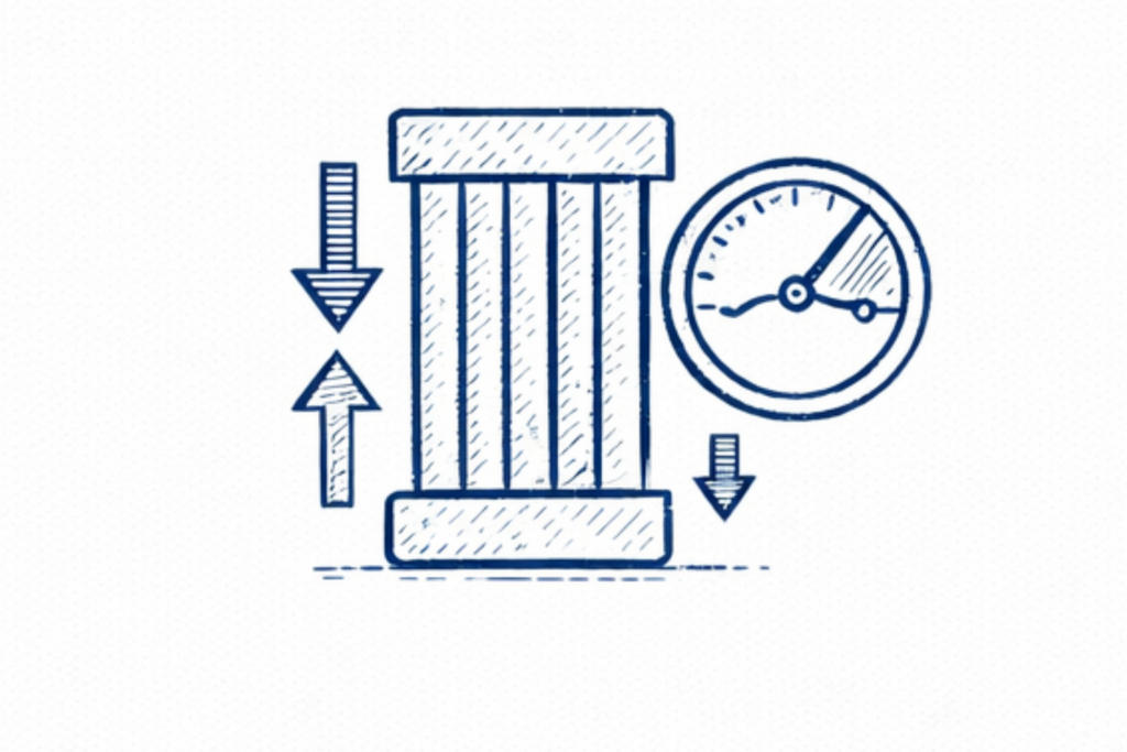
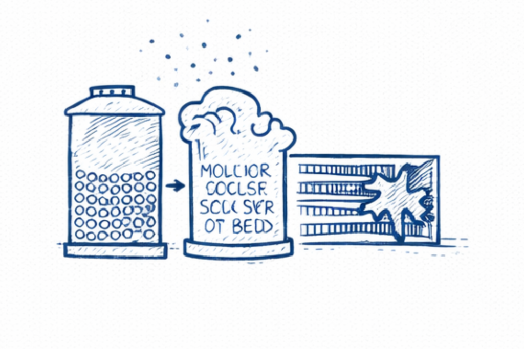
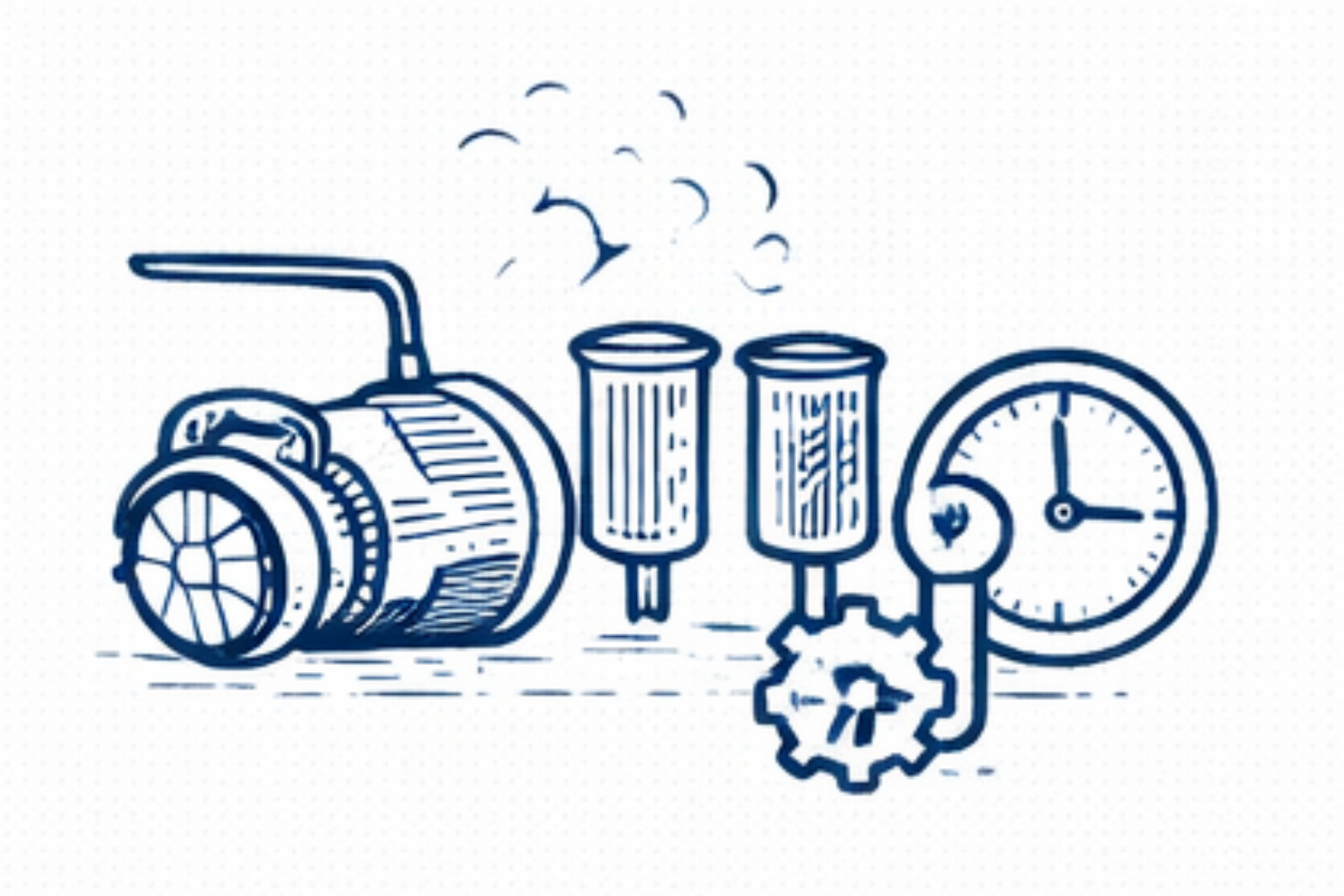
5. Adsorption Bed Pressure Drop Monitoring

The pressure drop across molecular sieve beds provides insight into adsorbent condition and bed performance. An abnormal increase in bed pressure drop may indicate: adsorbent degradation dust formation bed channeling These issues can reduce purification efficiency and allow contaminants to reach the heat exchanger.

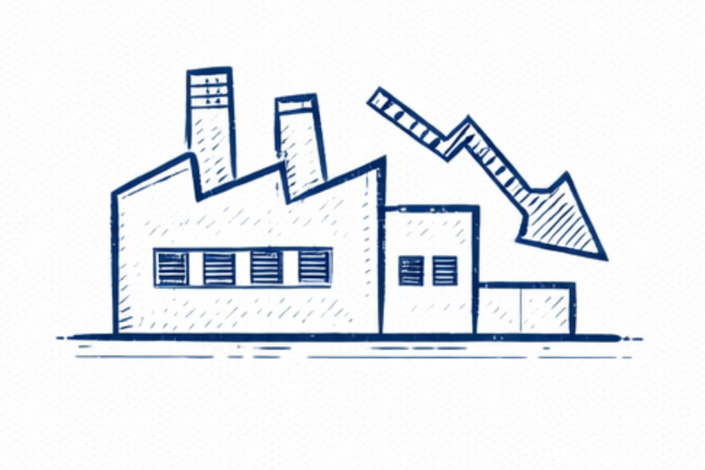
6. Plant Operating History Review

Engineers also review recent plant events that may have contributed to icing formation. Important events include: plant trips or emergency shutdowns rapid startup sequences unstable compressor or expander operation abnormal cold box temperature fluctuations These conditions can create situations where contaminants freeze within the exchanger passages.

This structured diagnostic approach allows engineers to identify whether heat exchanger icing originates from air purification system performance, process contamination, or operating instability, enabling targeted corrective action.

Key Engineering Insight

In many cases, cryogenic heat exchanger icing develops gradually rather than appearing suddenly. Small levels of contamination entering the cold box over time may slowly accumulate inside exchanger passages until operational disturbances become noticeable.

Continuous monitoring of purification system performance is therefore critical for preventing exchanger icing.

Engineering Solutions to Prevent Heat Exchanger Icing

Once cryogenic heat exchanger icing is identified, plant engineers must address both the immediate operational issue and the underlying cause of contamination or instability.
The goal is to restore stable plant operation while preventing future icing events.

Below are common engineering actions used to mitigate and prevent heat exchanger icing in cryogenic nitrogen plants.

1. Restore Proper Air Purification System Performance

The first corrective step is to ensure that the molecular sieve air purification system is functioning correctly.

Engineers should verify:

  • adsorption cycle timing

  • regeneration temperature levels

  • regeneration gas flow

  • correct valve switching sequence

Restoring proper purification performance prevents additional moisture or CO₂ from entering the cryogenic section.

2. Regenerate Molecular Sieve Beds Thoroughly

If contamination breakthrough is suspected, adsorption beds should be fully regenerated under correct operating conditions.

Adequate regeneration temperature and purge gas flow are necessary to remove trapped moisture and carbon dioxide from the adsorbent material.

In some cases, extended regeneration cycles may be required before returning the plant to normal operation.

3. Stabilize Cold Box Operating Conditions

Operational stability is critical for preventing ice accumulation.

Engineers should ensure that:

  • compressor load is stable

  • expander performance is consistent

  • feed air flow rate remains steady

  • temperature profiles remain within normal limits

Stable operation reduces the likelihood of localized freezing zones inside the heat exchanger.

4. Verify Moisture and CO₂ Monitoring Systems

Online analyzers used for contaminant detection must be accurate and properly calibrated.

Engineers should check analyzer functionality to confirm reliable monitoring of:

  • moisture concentration

  • carbon dioxide levels in feed air

Early detection of contamination allows operators to respond before icing develops.

5. Inspect Upstream Equipment for Contamination Sources

Upstream process equipment may introduce contaminants into the air stream.

Engineers should inspect:

  • air compressor lubrication systems

  • filtration units

  • air intake conditions

Preventing oil carryover or external contamination reduces fouling risks inside the heat exchanger.

6. Implement Preventive Monitoring of Pressure Drop Trends

Continuous monitoring of cold box differential pressure is an important preventive measure.

Tracking long-term pressure trends helps engineers detect early signs of exchanger blockage.

Early intervention can prevent severe icing that might otherwise require plant shutdown or extended maintenance.

Practical Engineering Insight

Heat exchanger icing rarely occurs without warning. In many cases, small operational indicators such as increasing pressure drop, temperature disturbances, or adsorption bed anomalies appear well before severe process instability develops.

Early identification of these warning signs allows engineers to correct purification issues before ice accumulation significantly affects plant performance.

Troubleshooting Guide for Cryogenic Heat Exchanger Icing

When cryogenic heat exchanger icing is suspected, plant engineers follow a structured troubleshooting sequence to confirm the presence of ice formation and identify its source. Because the main heat exchanger is located inside the cold box, diagnosis relies primarily on process data and operational trends. 

If exchanger icing becomes severe, the resulting instability may lead to cryogenic nitrogen plant trips triggered by abnormal pressure or temperature conditions.

The following troubleshooting approach helps engineers isolate the cause and stabilize plant operation.

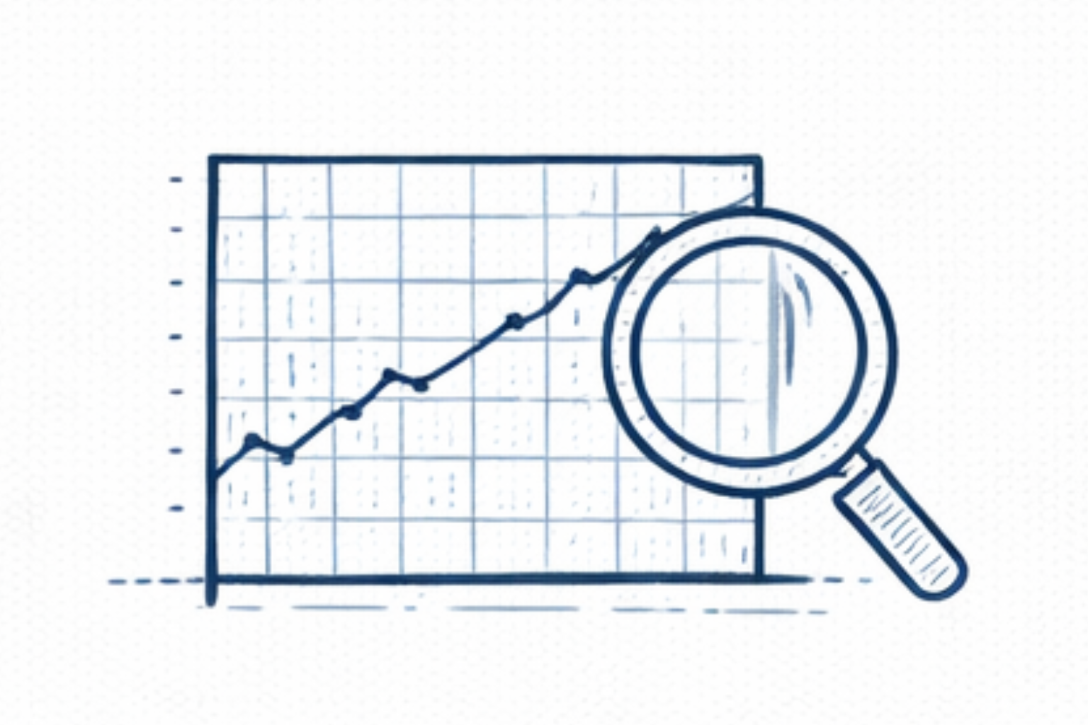
Step 1 — Review Cold Box Pressure Drop

Begin by analyzing the pressure drop across the cold box heat exchanger. A gradual increase in differential pressure is often the earliest sign of restricted flow caused by ice accumulation inside exchanger passages. Engineers compare current pressure readings with historical plant operating data to identify abnormal changes.

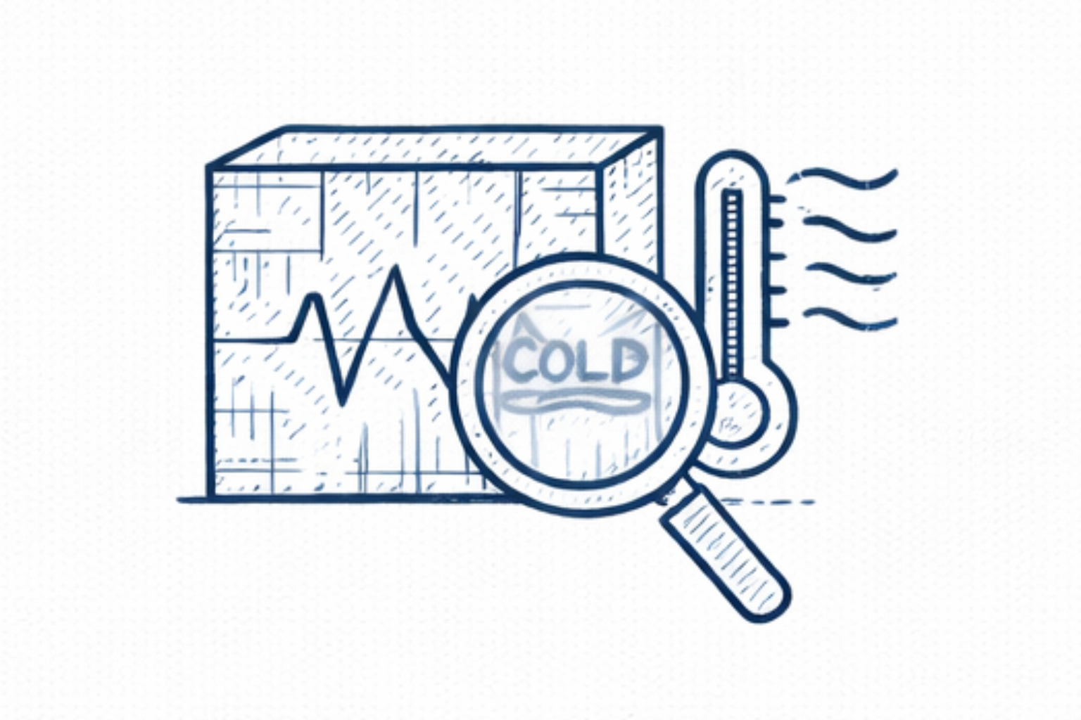
Step 2 — Examine Heat Exchanger Temperature Profiles

Next, review the temperature profile across the cryogenic heat exchanger. Abnormal temperature gradients or unexpected cold spots may indicate reduced heat transfer efficiency due to icing inside exchanger channels. Temperature sensors along the exchanger provide important diagnostic information.

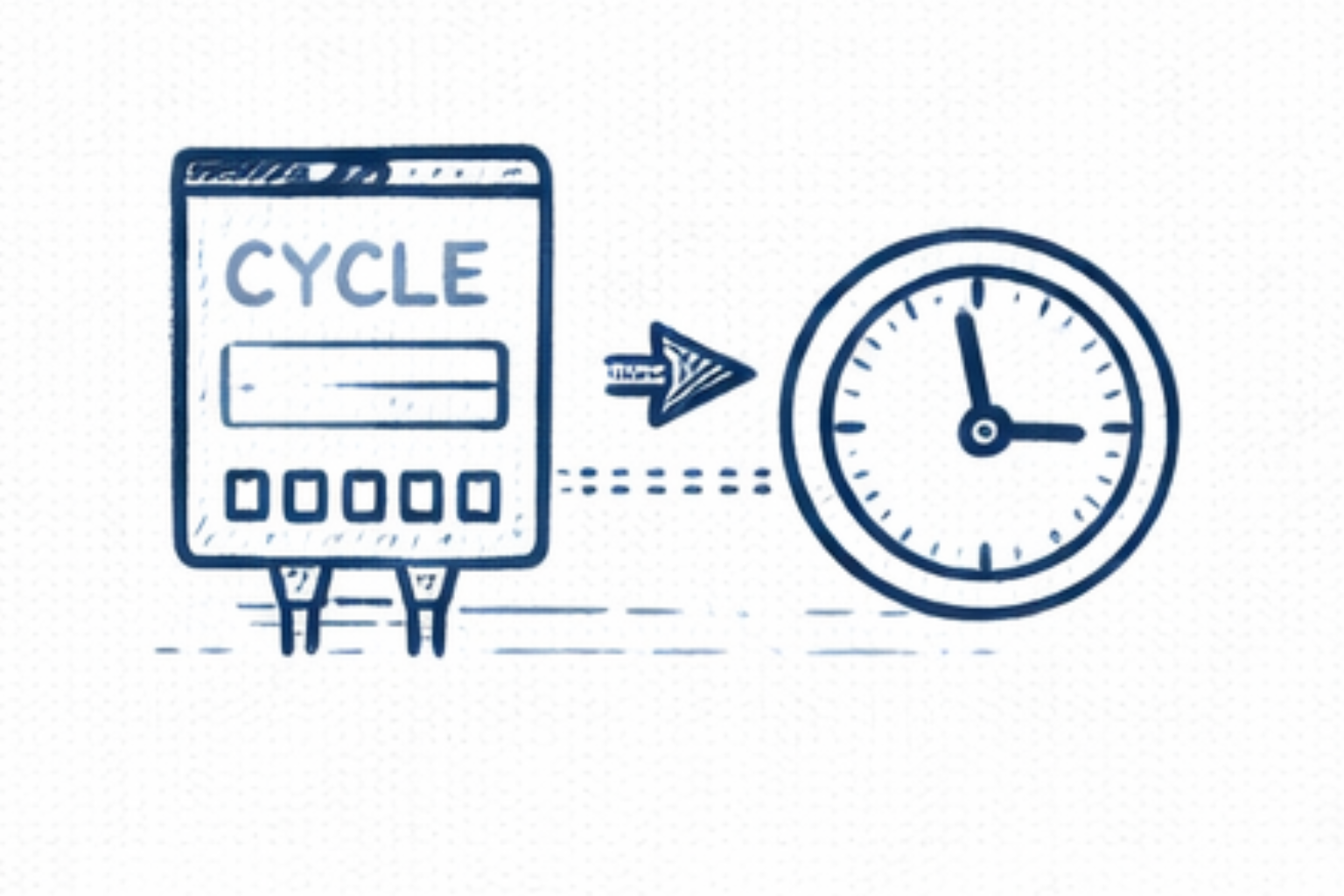
Step 3 — Check Air Purification System Operation

The air purification system should be carefully evaluated because icing is commonly caused by moisture or CO₂ contamination entering the cold box. Engineers verify: adsorption cycle timing regeneration temperature regeneration gas flow correct valve sequencing Any malfunction in the purification system can allow contaminants to pass into the cryogenic section.

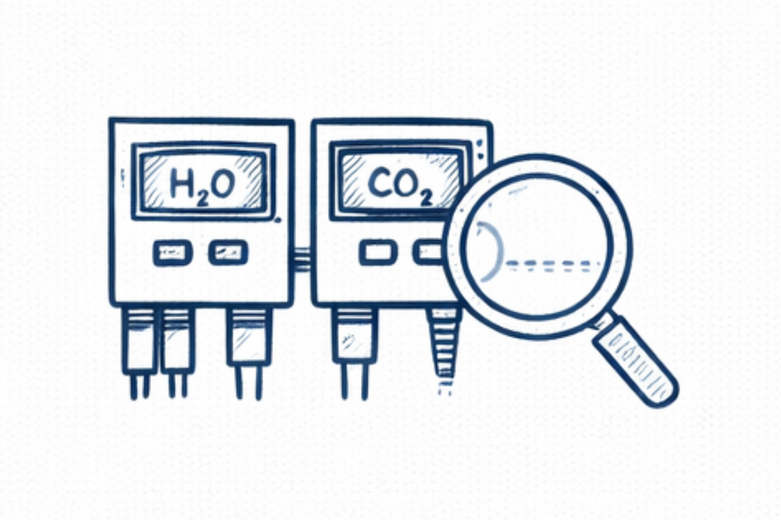
Step 4 — Verify Moisture and CO₂ Analyzer Readings

Online analyzers should be reviewed to determine whether contamination levels have increased. Engineers check analyzer calibration and confirm whether moisture or carbon dioxide breakthrough has occurred upstream of the cold box. Reliable analyzer data helps identify contamination problems early.

Step 5 — Inspect Molecular Sieve Bed Performance

Pressure drop across adsorption beds is monitored to evaluate adsorbent condition. Unusual pressure drop trends may indicate: adsorbent degradation bed channeling dust formation These conditions can reduce purification efficiency and increase the risk of exchanger icing.

Step 6 — Stabilize Plant Operation

If icing is confirmed, plant engineers may need to stabilize operating conditions or perform controlled plant shutdown procedures. Corrective actions may include restoring purification system performance, completing proper regeneration cycles, or adjusting operating parameters before restarting the plant.

Following a structured troubleshooting approach allows engineers to diagnose cryogenic heat exchanger icing effectively and restore stable plant operation while preventing further contamination of the cryogenic section.

Additional Engineering Support

Diagnosing cryogenic heat exchanger icing often requires careful evaluation of air purification system performance, cold box temperature profiles, and long-term operating trends. While many icing issues can be resolved through routine troubleshooting and operational adjustments, persistent contamination or repeated icing events may require deeper engineering analysis.

Plant engineers may benefit from structured diagnostic tools when investigating issues such as increasing cold box pressure drop, purification system instability, or recurring moisture and CO₂ breakthrough.

The Cryogenic Nitrogen Plant Troubleshooting Toolkit provides practical engineering resources including structured troubleshooting workflows, diagnostic checklists, and process analysis frameworks designed to support plant engineers during operational investigations.

For complex operational challenges requiring detailed process evaluation, specialized Cryogenic Nitrogen Plant Consulting Services are also available, where engineers can explore additional technical insights and professional support.

Conclusion and Key Takeaways

Cryogenic heat exchanger icing can significantly disrupt the operation of nitrogen plants by restricting airflow, disturbing heat transfer efficiency, and destabilizing temperature profiles within the cold box. Because the main heat exchanger is a critical component of the cryogenic separation process, even small levels of contamination can gradually lead to operational instability.

In most cases, icing develops when moisture or carbon dioxide bypasses the air purification system and freezes within the narrow passages of the plate-fin heat exchanger. Early identification of warning signs—such as increasing cold box pressure drop and abnormal temperature gradients—allows plant engineers to respond before severe operational problems occur.

Maintaining reliable performance of the air purification system, monitoring contaminant levels, and carefully reviewing plant operating trends are essential practices for preventing exchanger icing and ensuring stable long-term operation of cryogenic nitrogen plants.

Key Takeaways for Plant Engineers

• Cryogenic heat exchanger icing is typically caused by moisture or CO₂ contamination entering the cold box.

• Increasing cold box pressure drop is one of the earliest indicators of exchanger icing.

• Proper operation and regeneration of molecular sieve air purification systems are critical for preventing contamination.

• Continuous monitoring of temperature profiles and analyzer readings helps detect early signs of icing.

• A structured diagnostic and troubleshooting approach enables engineers to identify the root cause and restore stable plant performance.

Scroll to Top